Microstrip patch antenna & encapsulation of electronics
When designing wireless connectivity into Internet of Things (IoT) devices there are several options for antennas.
Rod Antenna
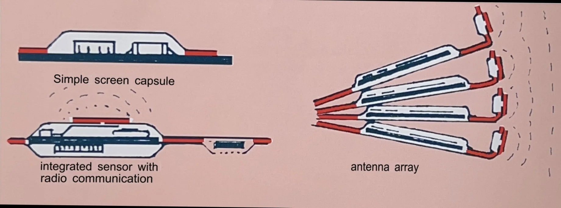
Different types of antennas can be integrated into PROOFCAP capsules. The Rod antenna can be connected to the circuit board and runs out through a small tunnel, with a diameter of about 2 mm, through the joint between the shell halves’ sealing area. The antenna wire is then prepared with an insulating layer of the same plastic material as the inner layer of the PROOFCAP laminate. This is then fused into the tunnel when the shell halves are sealed. This is a simple design that can satisfy many applications.
ACP Antenna
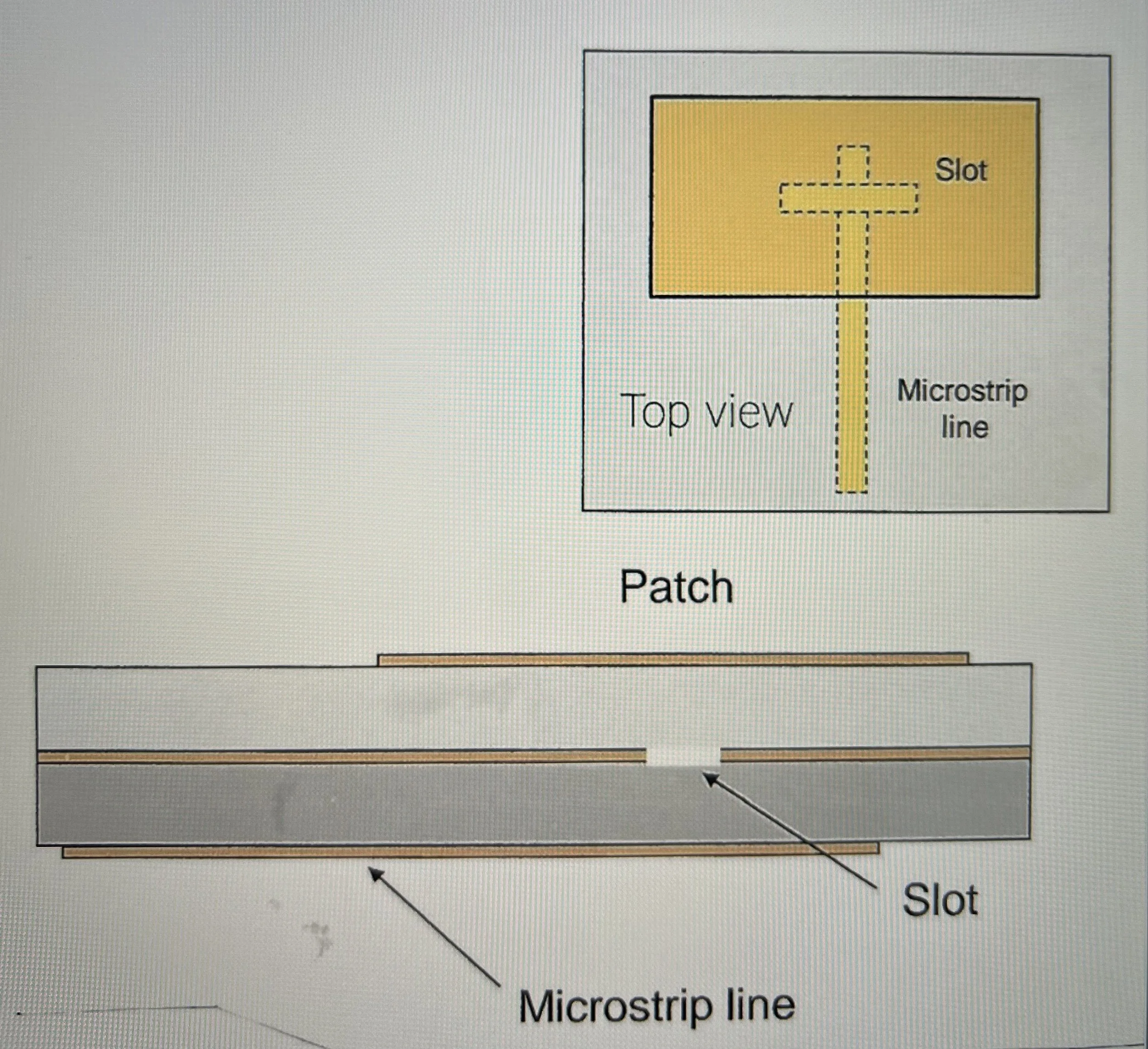
A more exclusive type is the microstrip-fed patch antenna. This variant offers some special advantages and can be designed in many different ways. The variant that fits best in PROOFCAP is the so-called Aperture-Couple-Patch (ACP). The signal is fed via a microstrip conductor, see figure below.
The ACP antenna has certain peculiarities and advantages that are known in the antenna design field and to this is that the diffusion distance for water molecules is very long, due to the metal layers having such a large overlap. (weater does not diffuse through metal). An additional advantage and possibility may be that the microstrip conductor is part of a circuit pattern with component assembly, which can be placed directly in connection with the output stage transistor and other components. The proximity of this integration and the reduced number of contacts will reduce losses and contribute to an antenna capsule that is very robust and has high efficiency.
PROOFCAP combines these properties with both moisture tightness and effective electrical shielding while the production technology is relatively uncomplicated and contributes to a capsule that is lightweight.
Microstrip Patch antennas are a popular choice for vehicle-to-vehicle communication, drones and other GPS-enabled devices. Effective in the GHz range patch antennas ensure precise navigation with optimal gain and radiation characteristics.
Microstrip patch antennas are used in satellite imaging systems, wireless communication equipment, military radios, aircraft, satellite and missile systems.
ADVANTAGES OF PROOFCAP INTEGRATED MICROSTIP PATCH ANTENNA
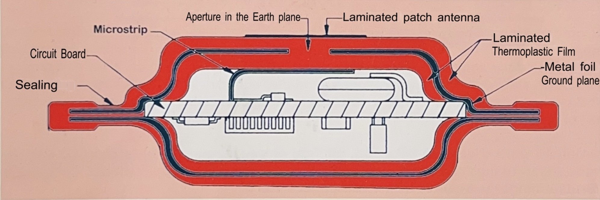
Patch antennas can be laminated directly into the surface of a ProofCap capsule. Such an antenna can have several different embodiments. One alternative version feeds the signal from a microstrip conductor that sits on the inside of the capsule, over the conductor is laminated a diel film and then a full-coverage ground plane foil that has a slot/aperture centered over the conductor. The path in the microstrip induces an alternating field that radiates up through the aperture and passes a full-coverage plastic film and hits a rectangular patch where the path pattern spreads. This is the antenna and it is covered by another plastic film. All of these plastic films are of a type that causes relatively low losses.
Inside the capsule, electronics for feeding the antenna arrangement can be connected via the microstrip. Such a device can be used for transmission and reception. If it is used for radar, the time between transmission and reception can be very short.
A microstrip conductor is a waveguide that conducts the path in its surface layer, the so-called skin effect, the current is thus concentrated in the surface of the conductor. Therefore, it is important that the conductivity of the conductor is high and that it is smooth and pore-free. One side of the conductor and the connections to the electronics must also have good conduction quality. A high-frequency radio signal can easily be degraded by losses both through radiation and by the energy being converted to heat.
In shielding tests carried out on the ProofCap, the only measurable radiation was that coming from the coaxial cable and connectors. Nothing came from the capsule.
To handle the optimization of Microstrip Patch Antennas collaboration is needed between Proofcap and antenna electronics designer.
In early shielding tests done on ProofCap, the only measurable radiation came from the coaxial cable and connector. There was nothing coming from the capsule.
The following factors favour proofcap with patch antenna
1) Water vapor is harmful because water has such a high permittivity and if the temperature drops, water films can also worsen the effect. Water can also cause corrosion.
2) Short signal lines have less losses.
3) Soldered connections that are properly dimensioned have less losses and are more mechanically stable than connectors.
4) Low weight is advantageous during accelerations.
5) For use at very high acceleration, the antenna part can be pressed into a spherical shape.
6) Proofcap is practically completely hermetic. Water vapor does not even enter through diffusion.
7) The patch is also protected against corrosion by a continuous plastic film.